This chart probably says it all, 28 transmissions logged Halloween evening on http://www.hfunderground.com, click to enlarge:
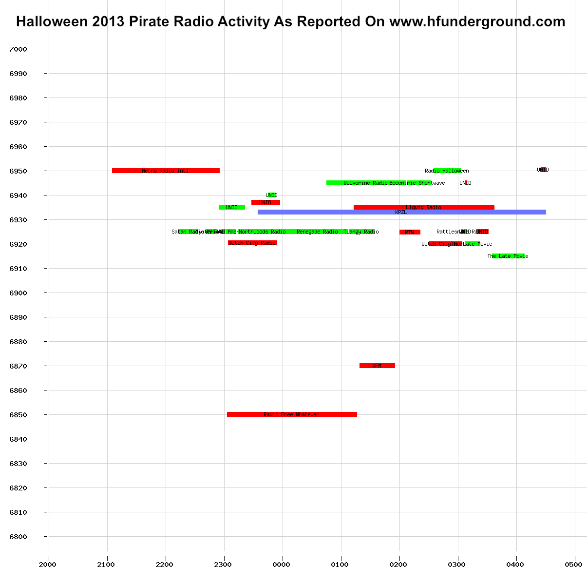

This chart probably says it all, 28 transmissions logged Halloween evening on http://www.hfunderground.com, click to enlarge:
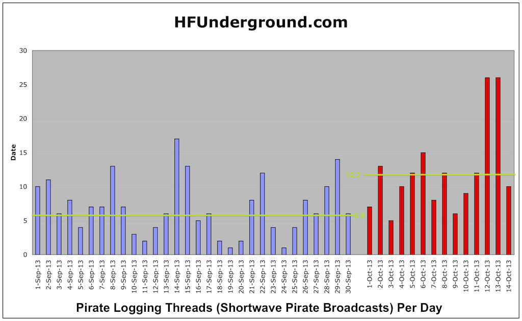
Here’s a graph showing the number of unique pirate logging threads on the HFUnderground.com
Each thread represents a different shortwave pirate radio broadcast. The red bars on the right are the number of broadcasts during the shutdown per day. I’ve also drawn in green the average number of broadcasts per day during the month before the shutdown (6.9 per day) as well as during the shutdown (12.2). As you can see, activity is up 77%. This past weekend was extremely active, setting records.
It’s markably easy to receive weather fax transmissions without a computer today, you just need an app for your smartphone or tablet, along with an appropriate shortwave radio. This can be extremely handy for mariners who do not have internet access at sea, but want to be able to receive weather charts to keep abreast of storms and other potentially dangerous conditions. It’s also a way for radio hobbyists to decode and view weather fax transmissions without using a computer.
For the iPhone, iPad, and iPod touch, there’s the HF Weather Fax app from Black Cat Systems, available on the iTunes store: https://itunes.apple.com/app/hf-weather-fax/id394199597?mt=8
An Android version is also available on the Google Play store: https://play.google.com/store/apps/details?id=com.blackcatsystems.weatherfax
Under good reception conditions, very high quality weather fax images can be received (click the image to see a full sized version): 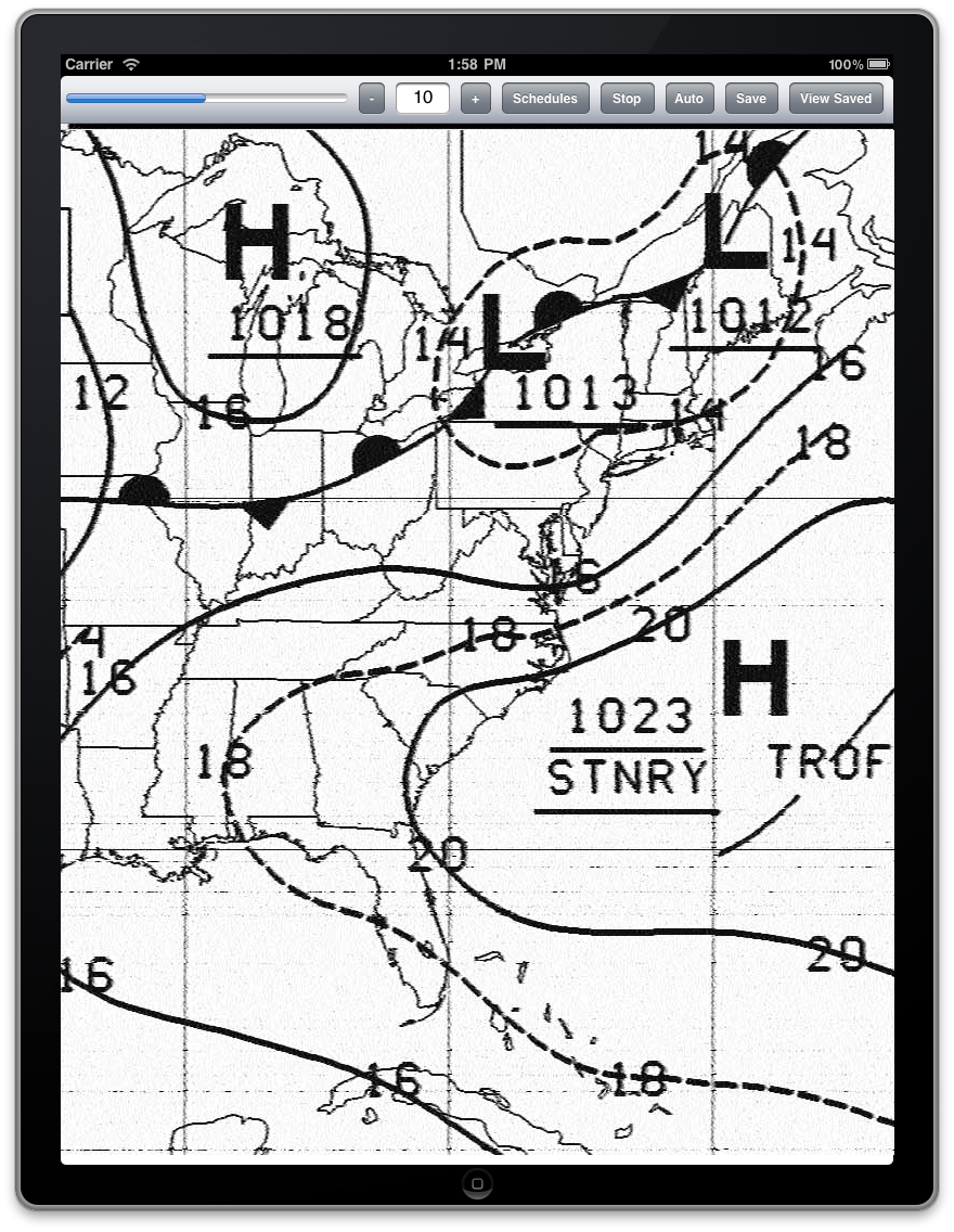
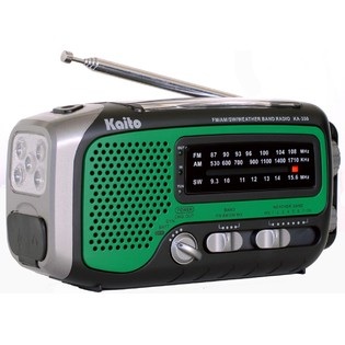
A radio capable of receiving the transmissions is also required. Most SSB marine radios should be able to do this, in addition there are many relatively low cost consumer radios that will also work, such as the Sony ICF-SW7600GR  .
.
Next, you need to get the audio from the radio into the tablet or smartphone. While there are some patch cables that will work, weather fax is fortunately a rather forgiving mode to receive, and often just placing the device’s microphone next to the radio’s speaker (or better yet next to some headphones plugged into the radio) often works quite well.
Weather faxes are sent several times a day from dozens of locations around the world. NOAA has their online Worldwide Marine Radiofacsimile Broadcast Schedules listing them by region and country, and is an essential resource. The frequencies listed are carrier frequencies, to tune them in USB mode on your radio, subtract 1.9 kHz. For example, NMF from Boston MA transmits on a carrier frequency of 6340.5 kHz. Your radio should be set to USB mode, and tuned to 6338.6 kHz for proper reception.
Both of these apps will automatically detect the start of fax tone sent at the beginning of an image transmission, to properly align the image. They will also detect the end of fax tone, and use that to save the image, for later viewing. Note that relatively good reception is required for proper detection of the start and stop tones, a weak signal or lots of static or interference (or even audio pickup from the microphone) can cause the tones to be missed.
Here’s a short video made by a user of HF Weather Fax on the iPad:
And here’s a video showing the Android app:
One downside to an SDR is that you more easily notice the mysterious carriers and other local noise/RFI signals. After reading this article on Common Mode Chokes, I decided to see what I could do to improve my situation.
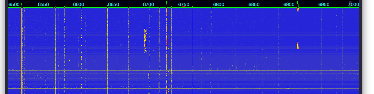
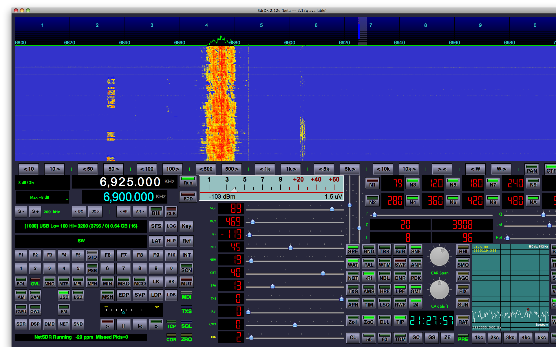
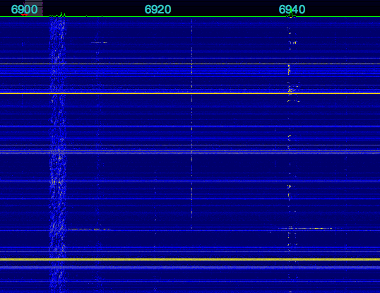
As a first step, I captured this baseline of the 6500-7000 kHz range, where I am most interested in listening (click to enlarge):
I then added a choke on the antenna input to the SDR, right where it enters the radio. It is 9 turns of the coax on a large toroid core, probably type 37 or 43 material, possibly a Fair-rite 5943003801:
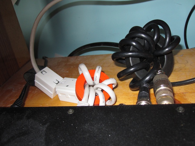
The other coax cable next to the antenna input is the reference signal from the 10 MHz GPS reference. Adding ferrite to it had no effect. I’ll get to the orange toroid next. Here is the result (click to enlarge):
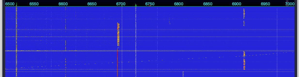
As you can see, there was a significant reduction in the number of carriers and other noise signals.
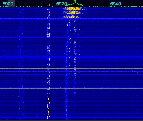
Next I added the orange toroid also pictured (unfortunately I have no idea what type of ferrite it was, it was from the junkbox), as well as two of the clamp on ferrites you often see on AC power or video cables to the ethernet cable that runs from the SDR to the computer, here are the results: (click to enlarge):
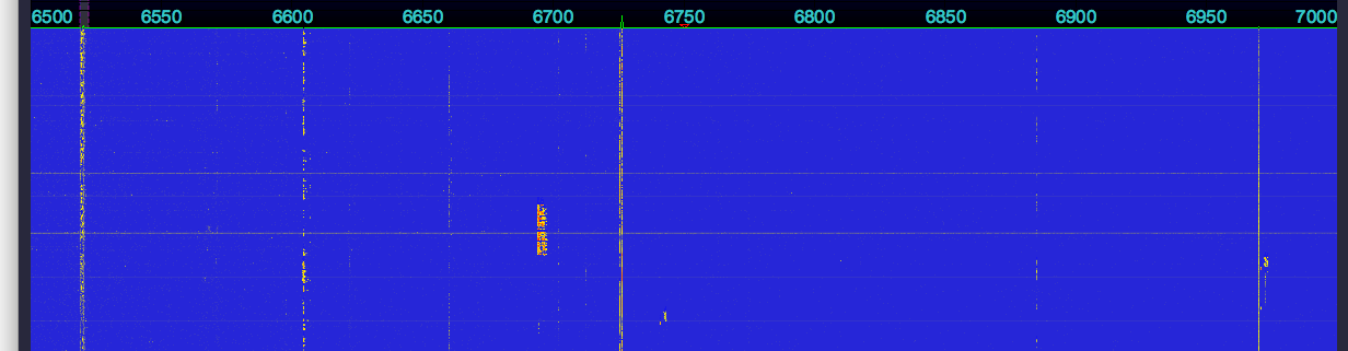
This got rid of a few more. Pretty much, what is left is an actual signal. I was able to identify these:
6604 New York Radio
6519 A voice transmission, perhaps another VOLMET
6660 The second harmonic of CHU 3330
6725 An RTTY transmission
6885 Israel fading in
6970 faded in and out, so it seemed to be a legit DX station
Here’s a slightly later shot of 43 meters (6800-7000kHz):
All in all, a significant improvement, for a few minutes worth of work!
Recently I had the need to measure the velocity factor of some coax. The velocity factor of a transmission line is ratio of the actual propagation of radio signals through the cable vs the speed of light in a vacuum.
Here’s the coax in question:
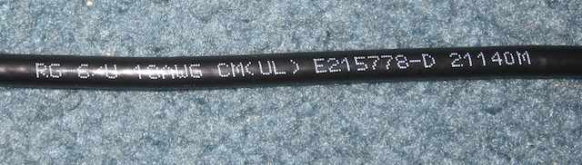
It’s RG-6U, for which I have seen published velocity factors ranging from 0.65 to 0.85, depending on the manufacturer and type of dielectric. This coax was laying in my junk box, and I have no idea who makes it, or what the claimed specifications are. The performance of a lot of lower cost coax often widely varies from published specs, as well.
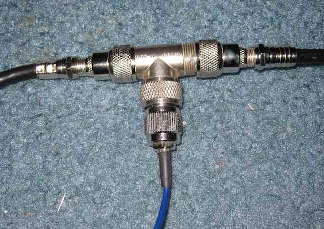
One technique to measure the velocity factor of a transmission line is to use a piece of it as an open stub, which is a section of transmission line connected to another line via a Tee connector. The added transmission line is open at the other end, hence the term “open” stub. The open stub will act as a notch filter for frequencies with a wavelength close to four times the length, in other words the stub is 1/4 wavelength.
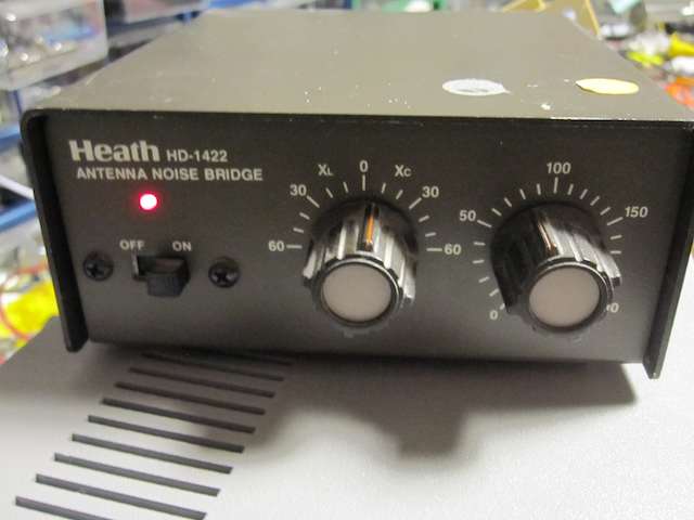
For this measurement, I used an SDR (Software Defined Radio) as the measurement device. In this case an SDR-14. To generate RF I used a noise bridge.
The output of the noise bridge is a good source of wide-band RF.
Here is the Tee. On the left is the RF signal, on the bottom is the connection to the SDR, on the right is the open stub.
With the noise bridge connected, but no stub, here is what the SDR spectrum looks like, click to enlarge:

As you can see it is relatively flat. Next, we’ll connect the 1/4 stub (again, click to enlarge):
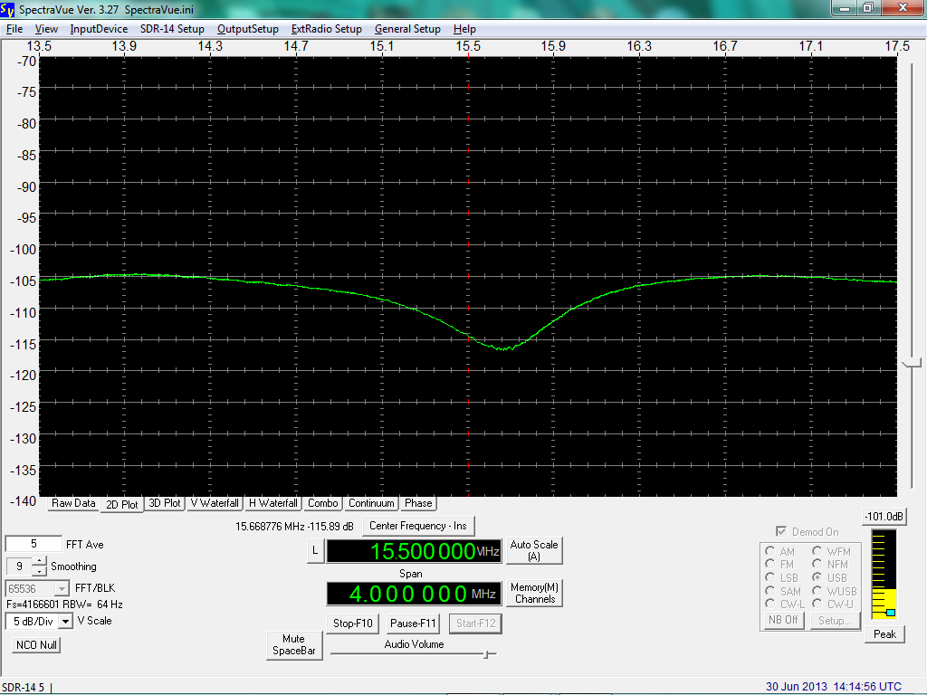
You can see the dip in the signal level, caused by the stub.
In this case, the stub was 13 ft (4 meters) of cable. Iif the velocity factor was 1.00 the wavelength would be 16 meters, the frequency 18.75 MHz. The frequency of the center of the notch is 15.7 MHz, so the measured velocity factor is 15.7 / 18.75 = 0.84.
Next I used a 9 ft 3 inch (2.85 meter) cable. The wavelength for a velocity factor of 1.00 would be 11.38 meters, the frequency 26.35 MHz. The frequency of the center of the notch was 21.8 MHz, so the measured velocity factor is 0.83.
Using both cables, the total length is 6.85 meters, the wavelength for a velocity factor of 1.00 would be 27.4 meters, the frequency 10.95 MHz. The frequency of the center of the notch was 9.1 MHz, so the measured velocity factor is 0.83.
For this piece of coax, the velocity factor seems to be 0.83, which is a reasonable value.
This weekend, I’ve noticed a station transmitting periodically on 6914 kHz. It will come on the air for a few minutes, then go off. All transmissions appear to be AM, with a variety of modes, such as CW (so MCW in this case), RTTY, and even some voice.
Last night I heard transmissions until the last one ended at 0136 UTC, when they stopped until 0745 UTC this morning. None were noted on the SDR recording during that time period.
When the transmissions restarted at 0745 UTC, they were extremely weak.
Here is an RTTY transmission (again, sent in AM mode) using 1000 Hz shift, 45 baud, with a center frequency of 1700 Hz, received at 2345 UTC 1 June 2013:
AGA5D2 DE A39P. FROM XXX DEFPAT ECHO X2 RTB XXXAFTER ACTION K

ART KKDUQLGLZXPQORU TUYI YUUOI PIOIU OUIYY WETYU IYOUI QRWET YTUII IUOPQ WYTUR TIOOQ PPOUY YYIER WEITY URYYU WQPOP TWLA IPQUQ QITWI PUPUQ IYUYR EWPQU TUIOW O

JAL4-6756 38677 192864 BT
A39P DE A5D2. ROGER OUT
The signal was not the best, so there are some errors in the decoded text. Here is an Audio recording of the transmission.
Here is a CW transmission at 1358 UTC on 2 June 2013:
And the decoded text, thanks to Token for providing it:
AHDR DE A50S COME IN K

A50S DE AHDR RGR GO AHEAD K

AHDR DE A50S CONTINUING ON SECPAT ROUTE.  ALL CONDITIONS NORMAL K

A50S DE AHDR RGR COPY ALL K
Here is a voice transmission at 1431 UTC on 2 June 2013:
Token has reported this station on both 6914 and 23146.5 kHz back in December 2012.
The STM32F4 DISCOVERY is a very neat development board for the STM32 F4 series microcontroller. Not only is it neat, but also cheap. As in $14.55. Here’s the link to buy one from Mouser.
I have some radio related projects that I plan on implementing with this unit. But first I had to get the Open Source development tools installed. And while there are numerous webpages that describe how to do this, none of them actually worked. Such is the world of Open Sores.
With a bit of help, I was able to get things up and running. To save others grief, I’m documenting what I did to get things working. First, a brief description of what goodies you get with this development board.

Here’s a datasheet for the development board.
Some of the Features:
■ STM32F407VGT6 microcontroller featuring 32-bit ARM Cortex-M4F core, 1 MB Flash, 192 KB RAM in an LQFP100 package
■ On-board ST-LINK/V2 with selection mode switch to use the kit as a standalone ST- LINK/V2 (with SWD connector for programming and debugging)
■ Board power supply: through USB bus or from an external 5 V supply voltage
■ External application power supply: 3 V and 5 V
■ LIS302DL, ST MEMS motion sensor, 3-axis digital output accelerometer
■ MP45DT02, ST MEMS audio sensor, omni-directional digital microphone
■ CS43L22, audio DAC with integrated class D speaker driver
■ Eight LEDs:
– LD1 (red/green) for USB communication
– LD2 (red) for 3.3 V power on
– Four user LEDs, LD3 (orange), LD4 (green), LD5 (red) and LD6 (blue)
– 2 USB OTG LEDs LD7 (green) VBus and LD8 (red) over-current
■ Two push buttons (user and reset)
■ USB OTG FS with micro-AB connector
■ Extension header for all LQFP100 I/Os for quick connection to prototyping board and easy probing

Now for the gory details of actually getting all this to work:
First, my system:
I installed this on a Mac Book Pro running Mac OS X 10.6.8. I wanted it on a laptop so I could take it to my basement workshop to do the actual development work. You can do this under linux and Windows as well. I don’t have any information on doing that, you’re on your own. Good luck.
I installed Xcode 4.2, which is the latest version that will run on 10.6 Snow Leopard. I understand that Xcode 4 is required to get the development stuff up and running, I do not know that for a fact, however.
First you need to install a bunch of stuff:
brew install mpfr gmp libmpc texinfo libusb-compat libftdi wget
This uses Homebrew, which you must install if you don’t already have it.
This toolchain script was used as the base: https://github.com/ehntoo/summon-arm-toolchain
As I said earlier, it does not quite work out of the box.
A big thanks to Gwynne who came up with a patch.
So all you need to do is:
cd && git clone git://github.com/ehntoo/summon-arm-toolchain.git && cd summon-arm-toolchain && wget -O - http://darkrainfall.org/build-openocd.patch | patch -p1 && ./summon-arm-toolchain
Then… wait. A while. It takes 20-30 minutes to build everything. Go have lunch.
All of the dev tools are put into ~/sat so make sure that is in your $PATH variable:
export PATH="$HOME/sat:$PATH"
Plug in the dev board and connect to it with the On Chip Debugger:
openocd -f board/stm32f4discovery.cfg
if all goes well, a bunch of text is spit out into the terminal window, ending with:
Info : stm32f4x.cpu: hardware has 6 breakpoints, 4 watchpoints
Then open up another terminal window and connect to the On Chip Debugger:
telnet localhost 4444
Next I grabbed the STM32 Discovery firmware files, to get some sample code:
git clone https://github.com/nabilt/STM32F4-Discovery-Firmware.git
I decided to try the IO_Toggle project first, which turns some digital outputs, connected to LEDs on the board, on and off. Toggling LEDs is the microcontroller version of a Hello World program.
Building the project did not go completely smoothly. I needed to change a line in the Makefile dealing with floating point:
MCFLAGS = -mcpu=$(MCU) -mthumb -mlittle-endian -mfpu=fpv4-sp-d16 -mfloat-abi=hard -mthumb-interwork
to
MCFLAGS = -mcpu=$(MCU) -mthumb -mlittle-endian -mfpu=fpv4-sp-d16 -mfloat-abi=softfp -mthumb-interwork
I don’t yet have a good explanation as to the need to make the change, but I saw it mentioned on many websites while searching for a solution to the problem.
The result is a demo.elf file which gets downloaded to the dev board.
Open up yet another terminal window (while in the directory containing demo.elf) and run gdb via:
arm-none-eabi-gdb
In the OCD telnet window, stop the program currently running on the microcontroller:
reset halt
Then in the window running gdb:
target extended localhost:3333

load demo.elf
Then in the OCD telnet window run the program:
reset run
I was rewarded with blinking LEDs. I then edited the main.c source code to change their toggle rate, and re-built the project, as a test, which all worked.
Next step, some radio related programming!
Mainstream radio engineering principles hold that the received signal strength of a transmission is proportional to the radiated power. Doubling the transmitter power produces twice the received power, quadrupling the transmitter power produces four times the received power, twice the received voltage, which is 6 dB or one S unit. This has been accepted for over a century.
However, recent experimental results, first reported on the FRN and later in The Journal of Irreproducible Results cast doubt in this basic radio engineering theory.
These results claim that as the transmitter power is reduced to very low levels, the received signal strength actually goes up, not down.
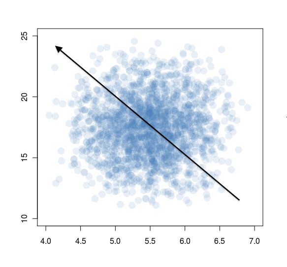
A transmitter location on the east coast of the USA was used. The tests were conducted on HF radio frequencies on and around 6925 kHz, using a state of the art solid state transmitter with a standard off the shelf MOSFET as the RF final amp:
![]()
Each monitoring post was equipped with the highest quality HF receiving gear and highly sensitive monopole receiving antennas.
During the trials, it was found that placing a non-conductive fabric, such as a sock, over the receiver produced the strongest signals. While the exact mechanism for this effect is not yet known, it is presumed to be due to the high dielectric constant of the fabric.
The results of the experiment clearly speak for themselves, as transmitter power went down, the signal strength went up:
One way to explain the results is to return to the luminiferous ether theory of radio propagation. Radio waves are propagated by vibrations in the ether. Fewer radio waves means that there is more ether per radio wave, so the vibrations are larger, producing a stronger signal at the receiving site.
There were even reports of radio propagation that cannot be explained by any known laws of physics, such as signals in the daytime traversing from Montana to New Zealand on 6955 khz with a completely sunlit path, even though D layer absorption would make this completely impossible. Yet this was reported many times by longtime radio physicist Dr. Winston: “The signals were always received with as SIO of 555. Even the audio quality was perfect, why it sounded like I was listening to it live in the studio!”.
Several times signals were actually received and logged on the FRN before the transmission began. This suggests that superluminal neutrinos may be involved.
Further research into this new phenomena is required. If homeopathic radio is ever perfected, it would allow listeners to report hearing transmissions that used little, or theoretically even no power. Indeed, reducing the output power to zero watts might produce the best results of all for this type of station.
Boom Box Radio had an early morning transmission on March 10, 2013, from 1044 until 1212 UTC. They were trying to reach a listener in Guatemala. The time of this transmission, starting just before to after sunrise, lets us examine the effects of sunrise on reception on the 43 meter band.
This first waterfall shows when Boom Box Radio signed on at 1044 UTC. You can see a very faint trace appear on the waterfall about a quarter of the way up from the bottom, at 6925 kHz. Remember that with a waterfall, time flows or falls down, like with a real waterfall, so the latest information is at the top:
This next waterfall shows what happened at 1107 UTC, when the signal went from just a faint trace of a carrier on the waterfall, and no audio, to a very good S7 to S9:
Note again that the oldest information as at the bottom of the waterfall. At that time, there is just barely a carrier. Then you start to see some modulation, and then finally, in a matter of seconds, the signal shoots up to armchair quality.
Below is a graph showing the signal strength of Boom Box Radio, in dBm, from 1044 UTC sign on, until 1212 UTC sign off. You can click on it to see a larger version:
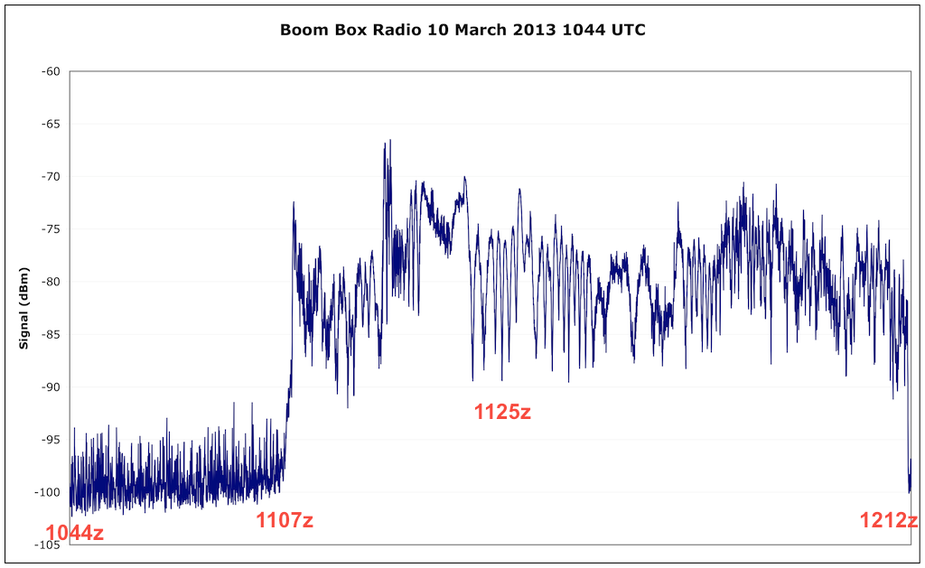
An S9 signal corresponds to -73 dBm. Every S unit is 6 dBm, so S8 is -79 dBm, S7 is -85 dBm, etc.
I have annotated several important times: The 1044 UTC sign on, 1107 UTC when the signal went up, 1125 UTC which was local sunrise, and 1212 UTC when it went off the air.
You can see that there is a very slow increase in signal level after the sign on, but the signal remains extremely weak. Then suddenly at 1107 UTC, the signal shot up to S9. Then for the rest of the transmission it mostly stayed in a range between S7 and S9.
The sudden increase in signal was caused by the Sun increasing the ionization level of the F layer of the ionosphere. This increase needs to have occurred at the point in the ionosphere where the radio waves are being reflected, most likely roughly midway between the transmitter and receiver locations. Note that in my case, this occurred before my local sunrise. This could be due two at least two factors I can think of. First, the transmitter site could be to my east. Second, the ionosphere is several hundred miles up, so it experiences sunrise before a point directly below it (on the Earth’s surface) does.
I believe this graph shows the importance of selecting the correct time for transmissions, depending on your target area. Just before sunrise is when the ionosphere is the weakest, and is only able to reflect radio waves on 43 meters at low angles. Too early in the morning, and the band is not open for local (NVIS – Near Vertical Incidence Skywave) reception. The band is, however, open for reception to more distant locations, that is, more than many hundreds of miles away (well over 500, perhaps close to 1,000 miles). If you’re trying to get out to DX locations, this is a good time to do it. Sunrise varies throughout the year, so as we move into summer, and it occurs earlier, the band will likewise open up earlier for NVIS. Likewise in the middle of winter in December, it is somewhat later.
For reference, the operator of Boom Box Radio stated that this was a Heathkit DX-60 transmitter putting out 40 watts into a 40 meter band dipole that was about 15 feet high.
I thank Boom Box Radio for conducting this early morning test.
Update: The operator contacted me again to mention that his local sunrise was at exactly 1107 UTC.
To gauge shortwave pirate radio activity in 2012, I analyzed the loggings to the HF Underground (http://www.hfunderground.com) message board. A computer script parsed the message thread titles, as well as the timestamps of the messages. This information was used to produce some statistics about the level of pirate radio activity. Of course, as Mark Twain has written: “There are three kinds of lies: lies, damned lies, and statistics.” Still, let’s see what we can learn.
There were 8683 messages posted to 2081 unique threads. Ideally, each thread represents an individual pirate station transmission. Also ideally, each message posted to a thread represents one logging. In reality, there is some error involved.
For example: the thread with the most messages, and therefore probably the most logs, and less probably the most listeners hearing it, was Wolverine Radio on October 19, 2012, with 39 messages. The numbers are slightly inflated, since a few reporters posted more than once. But it’s still a useful gauge how well heard a transmission was. If you’re interested, second place was a logging of an UNID on 3223 kHz on March 28, 2012, third place was Wolverine Radio again, on September 30, 2012, and fourth place was Pirate Radio Boston, on October 27, 2012. The UNID station had a lot of duplicate posts by individuals, which accounts for the high ranking.
The following graph shows the number of logging threads with a given number of messages:
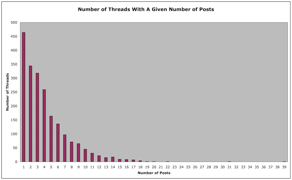
Looking at the graph, we see that there were 464 broadcasts with a single logging. 344 broadcasts had two loggings, 318 had three loggings, and so on. This tells us that the vast majority of transmissions were only reported by a small number of people. Over half were logged by three or fewer people, and three quarters by five or fewer people.
This of course does not mean that only that number of people heard the transmission. It is quite probable that the vast majority of pirate radio listeners do not log their reception reports on the HFU or any message board. Some may directly contact the station, while others listen but have little or no contact with other pirate enthusiasts or stations. Anecdotal evidence suggests there are a lot of “lurkers” in pirate radio, who may in fact be the vast majority of listeners. It is unfortunately impossible to come up with a good estimate of how large the pirate radio listening community really is.
If we assume each thread represents a unique transmission, then if we count the number of threads per pirate station, we can estimate how many transmissions they had. There are a few flaws with this method. First, it’s possible that there are some duplicate threads for a given transmission (two threads started by two listeners for the same transmission). This could inflate the estimate number of transmissions. Second, the loggings posted on the HFU represent what users heard and reported. There’s often stations that people hear but do not log, perhaps because they don’t get around to it, or because they’re not HFU users. Hang out on IRC #pirateradio for a while, and you will see many transmissions being mentioned, but never logged. This could make the estimated number of transmissions obtained by this method too low. Third, there’s also the question of what “counts” as a transmission. If a station was on for a few seconds with a test, but was logged by name, then it gets count. Finally there likely are some transmissions that no one heard, possibly due to poor propagation conditions.
Tabulating the information by station name, here are the stations with at least two or more transmissions logged on the HFU, sorted by number of transmissions (message threads):
Stations With Most Transmissions:
#1 Rave On Radio (85)
#2 Radio True North (82)
#3 Captain Morgan (81)
#4 Undercover Radio (79)
#5 Radio Ga Ga (66)
#6 Blue Ocean Radio (62)
#7 Wolverine Radio (51)
#8 Radio Ronin (49)
#9 Red Mercury Labs (42)
#10 WBNY (36)
#11 Turtlehead Radio (33)
#12 WMPR (32)
#13 XFM (23)
#14 Pirate Radio Boston (23)
#15 Renegade Radio (21)
#16 Channel Z (19)
#17 Metro Radio International (18)
#18 The Crystal Ship (18)
#19 WPOD (18)
#20 Big Boobs Radio (15)
#21 Grizzly Bear Radio (15)
#22 Voice of Captain Ron (15)
#23 Northwoods Radio (14)
#24 Toynbee Radio (14)
#25 Radio Bleh Bleh (13)
#26 MAC Shortwave (12)
#27 EAM Guy (11)
#28 Insane Radio (10)
#29 Northern Relay Service (10)
#30 Radio Free Mars Radio (10)
#31 Chamber Pot Radio (9)
#32 Liquid Radio (9)
#33 Radio 2012 International (9)
#34 Radio Free Euphoria (9)
#35 Radio Jamba International (9)
#36 Stone Circles Radio (8)
#37 WFMT (8)
#38 Eccentric Shortwave (7)
#39 All Along The Watchtower Radio (6)
#40 Appalachia Radio (6)
#41 Hot Legs Radio (6)
#42 KPZL (6)
#43 Mushroom Radio (6)
#44 PeePee Vagina (6)
#45 Radio Casablanca (6)
#46 Radio Strange Outpost 7 (6)
#47 WBOG (6)
#48 XLR8 (6)
#49 Pissant Radio (5)
#50 Radio Whatever (5)
#51 The Machine (5)
#52 WEMP (5)
#53 Ann Hoffer Live (4)
#54 CYOT (4)
#55 Radio Vixen International (4)
#56 KAOS (3)
#57 EAM Girl (3)
#58 Hard Tack Radio (3)
#59 KIPM (3)
#60 KMUD (3)
#61 WPON (3)
#62 Cool AM (2)
#63 Dit Dah Radio (2)
#64 Pandora’s Box (2)
#65 Radio Clandestine (2)
#66 Radio KEN (2)
#67 WHYP (2)
Not making this list are stations with only one transmission reported. Also, since the loggings were analyzed with a script, it is possible that
some logs were missed due to misspelling of the station name, etc.
And in reality, in #0 position way at the top, would be:
#0 UNID (534)
As you can see, there are a lot of UNID stations reported. Many of these are short test transmissions, or one or two songs played. Some are longer, full length transmissions, with either no attempt at an ID by the operator, or conditions were such that no listener was able to pull out an ID.
It’s worth pointing out, again, that these lists are based on the logs posted on the HFU. There are many reasons why a particular station’s broadcasts occurred but were not reported. The user base of the HFU is heavily centered around the Northeast and Midwest of the US. There could be transmissions from other parts of the country, particularly the West Coast, which are not being reported, because there are too few users from that region. There are also certain stations which some listeners have decided not to publicly log, for a variety of reasons.
Next, we can count the total number of loggings for each station, and see how they rank. Note that this is sensitive to duplicate posts by the same listener for a given transmission, so values for some stations can be inflated:
Stations With Most Loggings:
#1 Undercover Radio (429)
#2 Wolverine Radio (413)
#3 Captain Morgan (382)
#4 Radio True North (357)
#5 Rave On Radio (346)
#6 Radio Ronin (341)
#7 Blue Ocean Radio (288)
#8 Radio Ga Ga (229)
#9 WMPR (195)
#10 Red Mercury Labs (189)
#11 XFM (168)
#12 Turtlehead Radio (129)
#13 Renegade Radio (116)
#14 Channel Z (114)
#15 WBNY (108)
#16 Metro Radio International (96)
#17 Pirate Radio Boston (88)
#18 WPOD (74)
#19 The Crystal Ship (70)
#20 Big Boobs Radio (69)
#21 Grizzly Bear Radio (69)
#22 Radio 2012 International (62)
#23 Northwoods Radio (55)
#24 MAC Shortwave (54)
#25 Voice of Captain Ron (54)
#26 Toynbee Radio (53)
#27 EAM Guy (50)
#28 Radio Bleh Bleh (46)
#29 Liquid Radio (45)
#30 Radio Jamba International (45)
#31 Radio Free Mars Radio (45)
#32 WFMT (38)
#33 Hot Legs Radio (38)
#34 Radio Vixen International (38)
#35 Northern Relay Service (37)
#36 KAOS (34)
#37 Ann Hoffer Live (34)
#38 Radio Strange Outpost 7 (34)
#37 Mushroom Radio (33)
#40 Eccentric Shortwave (31)
#41 All Along The Watchtower Radio (31)
#42 Radio Casablanca (31)
#43 Insane Radio (29)
#44 XLR8 (28)
#45 KPZL (27)
#46 Appalachia Radio (27)
#47 Radio Whatever (27)
#48 KIPM (26)
#49 Radio Free Euphoria (26)
#50 WBOG (22)
#51 The Machine (22)
#52 Chamber Pot Radio (21)
#53 Pissant Radio (21)
#54 Hard Tack Radio (20)
#55 PeePee Vagina (20)
#56 Stone Circles Radio (19)
#57 Dit Dah Radio (15)
#56 Pandora’s Box (11)
#57 WEMP (10)
#58 WPON (10)
#59 KMUD (8)
#60 CYOT (7)
#61 WHYP (7)
#62 Radio KEN (7)
#63 EAM Girl (6)
#64 Cool AM (4)
#65 Radio Clandestine (4)
In general, the stations that transmitted the most, were reported the most. The largest exception to this rule is Wolverine Radio, which is #7 for total broadcasts, but #2 for total reception reports. Wolverine is often noted with a very strong signal, this may count for some of the larger ratio of reception reports to transmissions.
In fact, we can produce a table of the ratio of reports to transmissions for stations (with more than 10 transmissions, to reduce errors due to insufficient data). Stations with a high ratio have a lot of listeners per transmission, stations with a low ratio have few listeners per transmission:
8.10 Wolverine Radio
7.30 XFM
6.96 Radio Ronin
6.09 WMPR
6.00 Channel Z
5.52 Renegade Radio
5.43 Undercover Radio
5.33 Metro Radio International
4.72 Captain Morgan
4.65 Blue Ocean Radio
4.60 Big Boobs Radio
4.60 Grizzly Bear Radio
4.55 EAM Guy
4.50 Red Mercury Labs
4.50 MAC Shortwave
4.35 Radio True North
4.11 WPOD
4.07 Rave On Radio
3.93 Northwoods Radio
3.91 Turtlehead Radio
3.89 The Crystal Ship
3.83 Pirate Radio Boston
3.79 Toynbee Radio
3.60 Voice of Captain Ron
3.54 Radio Bleh Bleh
3.47 Radio Ga Ga
3.00 WBNY
The average ratio is 4.75.
If we look at the estimated number of broadcasts by day of week, the results are inline with what we expect, namely that the weekends are most active, with a lull during the middle of the week:
Sunday 485
Monday 205
Tuesday 174
Wednesday 173
Thursday 173
Friday 320
Saturday 551
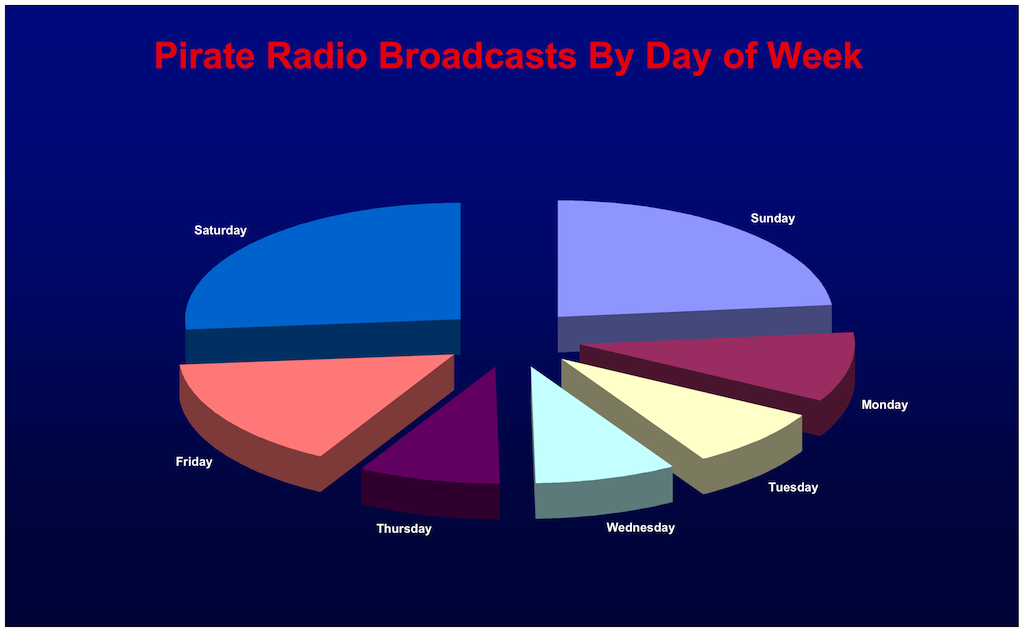
However, even the days in the middle of the week (Tuesday, Wednesday, and Thursday) have some level of pirate activity, about 3 or 4 transmissions per day. This is a very high level of activity as compared to what I remember from the 1980s and even the 1990s. Back then, weekday transmissions were much less common.
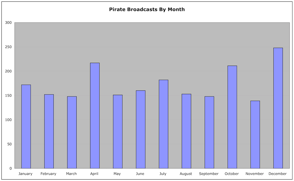
Breaking down the activity by month, we see there is some variation, with the busiest month, December (as we’d expect, with all the holidays) a little less than twice as active as the slow months in the Spring:
January 172
February 152
March 148
April 217
May 151
June 160
July 182
August 153
September 148
October 211
November 139
December 248
Looking at the transmitting modes used, AM and USB are virtually tied, with USB having a slight edge. The other modes are literally noise, with a small handful of reports. There’s a significant number of logs where no mode was reported, but it is virtually certain that either AM or USB was used:
AM 822
USB 849
LSB 21
CW 29
FM 21
SSTV 65
UNKNOWN 274
And what about the choice of transmission frequency? 6925 is the big winner, accounting for over half, and close to two thirds, of the logged broadcasts. If you add in the logs for 6924 kHz, which no doubt are pirates trying to end up on 6925 but who have a crystal or VFO that is slightly off, you end up with an even larger total. Clearly, if you can only monitor one pirate frequency, 6925 is the one:
6240 kHz: 4
6850 kHz: 5
6899 kHz: 9
6900 kHz: 12
6920 kHz: 5
6924 kHz: 82
6925 kHz: 1343
6926 kHz: 7
6927 kHz: 6
6929 kHz: 5
6930 kHz: 132
6932 kHz: 4
6933 kHz: 8
6935 kHz: 75
6940 kHz: 47
6945 kHz: 24
6949 kHz: 6
6950 kHz: 104
6951 kHz: 11
6955 kHz: 39
11428 kHz: 5
15070 kHz: 16
There are still a significant number of transmissions on other frequencies, with 6930 and 6950 being the most popular. 6955, which at one time was the most used pirate frequency in North America, is now down to 6th place, lower than the number of broadcasts by ops on 6925 kHz with a off frequency crystal.
Your comments, questions, and suggestions are greatly appreciated!